RiggerSafe Doctrine™ Field Notes
Project Sales Corp / HSI
Five RiggerSafe
Moments
Where inherited hand behaviour meets a suspended load — and how lift planning can prepare a different response before the impulse arrives.
It rarely begins with a dramatic movement.
A beam rotates by a few degrees. A cargo basket drifts towards the deck edge. A transformer approaches its foundation slightly out of alignment. A pipe spool arrives with its flange facing the wrong direction. A fabricated module descends with one corner leading.
The rigger sees it. The correction appears obvious. The distance looks manageable. The movement seems slow.
The hand begins to rise.
That movement is not necessarily carelessness. It may be experience responding to a familiar problem. The rigger wants to protect the load, achieve the alignment and complete the lift.
But the load is still suspended.
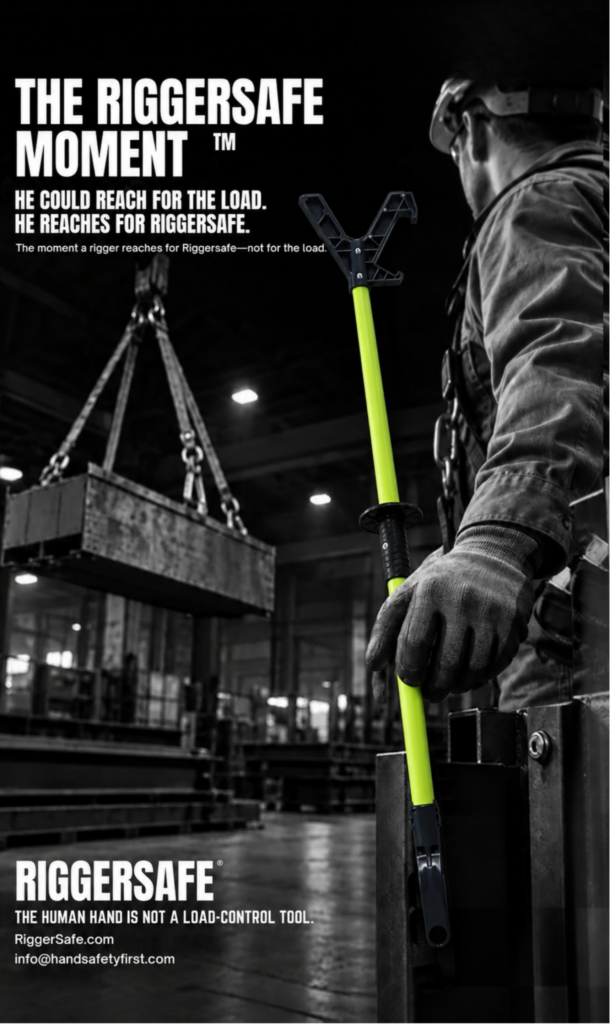
The instant a rigger feels the impulse to reach towards a suspended load — and instead uses the planned appropriate tool.
No two lifting operations are identical. Loads differ in mass, shape, centre of gravity, rigging configuration and behaviour. Worksites introduce different clearances, surfaces, weather conditions, structures and operational pressures.
Yet one behavioural pattern appears across industries. The load approaches a point at which someone feels the need to touch it. That impulse may arise during rotation, drift, alignment, orientation, landing or final positioning. It may occur in a shipyard, fabrication shop, steel plant, offshore installation, transformer factory or construction project.
The purpose of the RiggerSafe Doctrine™ is to identify that moment before the lift begins.
The following five scenes show what that decision can look like across heavy industry.
The beam has cleared the ground. Its long profile hangs beneath the crane, travelling steadily towards its supports. The rigging appears stable. Then the beam begins to rotate.
The movement is gradual. One flange advances while the other retreats. At first, the change seems insignificant. The rigger recognises it immediately — and his hand moves.
THE INSTINCTIVE ACTIONPush the flange directly, catch the leading edge or grip the beam to resist its rotation. The action feels natural because the movement is slow and the beam appears responsive.
THE EXPOSUREThe beam's length amplifies apparently minor movement. Rotation may bring the rigger towards a support, column or another worker. The hand may enter between the beam and its landing point. The beam remains suspended — its movement is controlled by crane, rigging geometry and load distribution, not by the hand placed against it.
THE PRE-PLANNED CONTROLBefore lift-off, Find the Hand™ identifies rotation as the point at which direct contact is likely to enter. The lift team establishes expected orientation, worker positions, selected rotation-control method, closing interfaces near supports, and the movement that requires the lift to stop.
Where the risk assessment determines a push-pull tool is appropriate, RiggerSafe® is inspected and positioned before the beam is lifted.
A slowly rotating beam is still moving with more authority than the hand placed against it.
The cargo basket approaches the deck. The crane operator lowers steadily. Then one corner begins travelling away from the intended landing point.
A deck rigger steps towards it. The impulse is immediate: grab the frame, steady the corner and bring it back.
THE INSTINCTIVE ACTIONGrip the basket frame, catch a corner or hold the load steady while it descends. The action may be familiar — and familiarity can make exposure feel ordinary.
THE EXPOSUREA drifting basket can close distance quickly. A hand or arm may become trapped between the basket and deck equipment, a fixed structure or the landing surface. Environmental movement can change the load's behaviour after the rigger has committed to contact.
THE PRE-PLANNED CONTROLThe plan addresses environmental limits, basket approach, deck-crew positions, taglines, the selected final-positioning method, escape routes and conditions requiring the basket to be lifted away. The fact that the basket has reached the deck does not mean the suspended-load exposure has ended.
RiggerSafe may be appropriate only when the basket remains controlled and movement is predictable — not to catch a swinging basket or recover one already moving outside the plan.
The transformer has travelled across the assembly area. Its mass is obvious, but its movement has been deliberate and controlled. Now the final alignment begins. The mounting points are close — but not exact. One side appears slightly offset. The remaining movement is small enough to make touch seem reasonable.
The rigger studies the gap. His hand rises towards the casing.
THE INSTINCTIVE ACTIONPress against the casing, guide an edge or place a hand near the foundation to judge alignment. The hand appears capable of providing the fine correction and sensory feedback required.
THE EXPOSUREThe foundation creates fixed interfaces around a suspended load. As the transformer descends, clearances narrow and gaps close. Hands and fingers near mounting points or foundation edges can become exposed to crushing or trapping movement. A load does not become safe to touch because it is only millimetres from its destination.
THE PRE-PLANNED CONTROLThe Last 300 mm Rule™ directs attention towards the final positioning zone before precision becomes urgent. The lift plan identifies required alignment tolerance, guides or engineered positioning aids, how orientation will be controlled, where workers will stand, which gaps will close, and when the transformer must be raised and repositioned.
The smaller the remaining distance, the less space there may be for error or withdrawal.
The pipe spool reaches the installation area. Its route has been controlled. But the spool is not correctly oriented. One flange is several degrees away from the required position. The correction looks simple: grip the pipe and twist.
The rigger reaches towards the spool.
THE INSTINCTIVE ACTIONGrip the pipe, flange or elbow and use the hands to rotate the suspended spool. The curved surface and manageable speed can create an illusion of control.
THE EXPOSUREPipe spools can rotate unexpectedly as rigging tension, centre of gravity and contact conditions change. A flange may move towards a structure or installation point. The hand can be drawn towards a narrowing interface as the spool approaches connection points.
THE PRE-PLANNED CONTROLFind the Hand™ asks the team to identify orientation as an expected intervention point before lift-off. The team determines the spool's intended orientation during travel, how its centre of gravity may affect rotation, whether rigging can pre-orient it, the control selected for final adjustment, and stop-work criteria.
Orientation is part of the lift — not a hand task left for the installation point.
The module descends towards multiple supports. The landing points are visible. The rigging remains under tension. One corner approaches first. The crew can see that the module will not settle evenly.
A rigger moves towards the leading corner. The impulse is to push it across, protect the support or stop the edge from landing incorrectly.
THE INSTINCTIVE ACTIONPush the leading corner, steady an edge, protect a support or place a hand near the landing interface to guide the module into position. The action is driven by a desire to prevent damage and complete the landing correctly.
THE EXPOSUREA module supported at several points may change orientation as one corner contacts first. Rigging loads can redistribute. The module may settle, tilt or move laterally. The landing points create several closing interfaces at once. A rigger concentrating on one corner may not see movement developing elsewhere.
THE PRE-PLANNED CONTROLThe final landing method should define the intended sequence of contact, acceptable level and orientation, how uneven approach will be recognised, crane hold and correction signals, worker positions at every corner, the planned means of influence, escape routes and the point at which the module must be raised and the landing reset.
RiggerSafe may be appropriate while the module remains suspended, controlled and within the planned positioning envelope. It does not allow the rigger to stand between the module and its supports or remain near a corner that may suddenly settle.
The lift is not complete when the first corner touches. It is complete only when the load has landed as planned and the lifting team confirms the condition.
What connects all five moments
The steel beam, cargo basket, transformer, pipe spool and fabricated module are different loads. But the behavioural sequence is similar:
If the alternative has not been selected, inspected and positioned before the lift, the hand remains the most immediately available response.
That is why the RiggerSafe Moment™ cannot be created merely by issuing a tool. It must be designed into the task. The team must Find the Hand™. The final positioning zone must be examined through the Last 300 mm Rule™. The intended control and worker position must be agreed. The conditions requiring the lift to stop must be understood.
Then, when the impulse appears, the rigger has somewhere safer for the hand to go.
The human hand is not a load-control tool.
RiggerSafe® is intended only for applications in which the task-specific lift plan, risk assessment and designated lifting authority determine that a push-pull tool is appropriate. RiggerSafe does not make an uncontrolled load safe. It does not replace:
The tool must not be used to catch, arrest or recover an uncontrolled load. Its length does not authorise anyone to enter an exclusion zone or stand in the potential path of a load. If movement becomes unpredictable, communication fails, visibility is inadequate, the escape route is obstructed or the task departs from the lift plan — invoke the applicable stop-work process.
Find the Hand. Make a different decision.
Before the beam rotates — find the hand.
Before the basket reaches the deck — find the hand.
Before the transformer approaches its foundation — find the hand.
Before the spool needs orientation — find the hand.
Before the module begins landing — find the hand.
Examine the last 300 mm.
Name the impulse.
Position the planned control.
Protect the escape route.
Define the stop conditions.
Then let the hand make a different decision.
Not towards the suspended load — towards the appropriate tool already selected for the task. That decision is the RiggerSafe Moment™. And repeated across crews, sites, industries and countries, that moment becomes more than an individual action. It becomes the new way the work is done.
The RiggerSafe Moment is not created by issuing a tool. It is designed into the task.
Orientation, alignment and landing are part of the lift — not hand tasks left for the destination.
The objective is not to make the rigger less responsive. It is to prepare a better response.
RiggerSafe® is a push-pull tool system developed for controlled final positioning of suspended loads in heavy industrial lifting operations. Manufactured and distributed by Project Sales Corp / Hand Safety India (PSC Group), Visakhapatnam, India.
Web: riggersafe.com PSC: pscvizag.com
This article is part of the RiggerSafe Doctrine™ field notes series. It does not replace site-specific lift planning, risk assessment or the authority of the designated lifting supervisor.